Updated 11/12/22

Pyromania is a rocket I wanted to build years ago. I received an M1419W as a gift during my summer at NASA in 2018, and ever since I’ve wanted a rocket in my fleet to support a 98mm motor. The 5″ Blue Iguana kit from Madcow/Rocketry Warehouse seemed to be discontinued in 2021, but AMW had one last one that I managed to pick up. The build process is documented below. It isn’t anything special other than that it’s the biggest personal rocket I own. It’s just over 10ft tall and is fun to fly! Below is the OpenRocket file for the completed rocket, and there’s another link to the kit’s parts by itself further down. 

0
Total flights

Flight Log

  1. 11/12/22 – Argonia, KS. 
    Motor: Aerotech M1419W
    Apogee: 12075ft (3680m)

Parts and Initial Sim

2/6/22

The parts from the kit were measured, weighed, and entered into OpenRocket. This kit didn’t contain any hardware, rail buttons, decals, or recovery. I’ll mentioned where I sourced all the additional parts when I acquire them. 

Parts BOM:
1. 60″ aft airframe section
2. 2″ slipband
3. 30″ payload airframe section
4. 30″ nosecone (with aluminum tip)
5. 7.5″ nosecone coupler
6. 12″ avbay coupler
7. 22″ 98mm motor mount tube
8. (3) trapezoidal fins
9. (3) centering rings
10. (1) nosecone bulkplate
11. (2) stepped avbay bulkplate lids

5" Blue Iguana Kit from Rocketry Warehouse

Thrust Plate & Motor Mount Assembly

4/16/22

I finally got the parts needed to put together the motor mount assembly. The 5/98 thrust plates from SC Precision were hard to come by, but these thrust plates are awesome, especially for the 98mm flanged retainers from Aeropack. That was also needed to properly build this section, but now with all parts in hand, I got started. 

I had some flange nuts left over from projects when I was still at OSU, so I used these along with countersunk screws to attach the thrust plate to the aft-most centering ring. I sanded down the ring to slip over the 98mm motor mount tube, and marked the 3 countersunk hole locations for the flange nut holes. I widened one end with a 3/8″ bit so they’d sit more flush.  

Nested the centering ring below the thrust plate and marked the (3) hole locations
Flange nut locations
Bevel for flange nut to sit more flush

For the narrow (0.5in) centering ring width, I trimmed down the sides with a Dremel cutting wheel and sanding bit to roughly match the curvature of the ring. I scuffed up the bonding side with 60-grit sandpaper and bonded them into the holes with 5-minute epoxy. 

Curvature marked in Sharpie
Trimmed to fit centering ring
Trimmed nuts in place
No overhang

To install onto the motor mount tube, I screwed the thrust plate to the centering ring with about a half inch of offset to keep any epoxy from also bonding the thrust plate in place. I fitted the thrust plate and centering ring onto the motor mount, applied a few grams of G5000 Rocketpoxy and pushed the assembly until thrust plate was flush with the edge of the motor mount tube. 

Finally, I also screwed on the retainer to hold the bonding location of the centering ring in place during cure. That was probably the most challenging part of this whole rocket, so from here it should be much more familiar! 

Thrust plate and ring prior to bonding
Retainer attached to hold bonding location

Ended this installation with the upper 2 centering rings installed above where the fins will bond.  

Motor Mount Installation

5/16/22

For bonding the motor mount assembly into the aft airframe section, I roughed up the interior of the airframe common to the centering rings, the motor mount tube at the fin bonding areas, and sanded down the centering rings until the assembly could slide into the airframe without too much trouble. I also drilled out (6) 1/4″ holes next to each fin slot for injecting fillets after the fins are attached. I did the drill-out now so I could deburr and the fiberglass dust wouldn’t cover the inside parts. 

1/4" holes for injecting fillets later. Rail button hole aft.

The last bit of prep was drilling the 3/16″ hole for the 1515 rail button flange nut. I’m sure there are better ways to do this, but I usually install the aft rail button when the motor mount assembly is partway pushed in. 

I put about 15g of epoxy inside the prepped airframe forward of the fin slots and pushed the assembly nearly to the end of the fin slots. There I paused to install the rail button with flange nut with some epoxy on the flange to bond against the tube. I applied an additional 4g of epoxy inside the airframe for the aft centering ring before the assembly was pushed the rest of the way down. I used another 4g of epoxy to bond the aft centering ring from below also, keeping the threads of the flange nuts clear. Lastly to hold the exact depth and location into the tube, I temporarily installed the thrust ring to maintain placement. 

Once it all cured, I screwed the thrust plate in place, and that wrapped up the motor mount installation!

Aft centering ring installed
Aft cure, thrust plate secured
Thrust plate and 98mm motor mount are flush, thrust plate installed. Aeropack retainer screws on above.

Initial Fin Installation

8/2/22

After a 2-month break in which I moved, I’m back to building! I taped over the fin slots, so other than sanding the fin tabs, I was good to jump right into getting the fins installed. Since I’m trying injected fillets, I minimized the epoxy on the motor mount tube-fin join compared to what I’d usually do. I masked off most of the joint, both on each fin and the external airframe, and applied just enough Rocketpoxy to essentially wet the fiberglass areas to be bonded. 

Masking off all but a narrow area for the initial bond

Next, I’ll then inject fillets with West System epoxy, and apply thick external fillets with Rocketpoxy (and black pigment) to cover it all up. I won’t bother with any tip-to-tip glassing unless a fin breaks off at some point. Hopefully it never needs it because there will already be plenty of epoxy around this fin can as is!

Fin in place
Masking peeled away and cured
Big rocket in the shop is coming together!

Fin Fillets

9/25/22

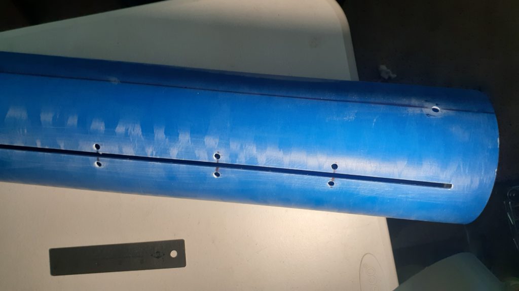
After getting the fins bonded in place, I did injected fillets using 30g of West Systems epoxy per fin, with a pinch of chopped carbon fiber. With the opaque fiberglass, it was really hard to tell how well it was distributed along the root of each fin, and one of the first fillets somehow ran down along the length of one fin, around the motor mount tube, pooled along the bottom fin, and ran out one of the injection holes down the bottom-hanging fin and onto the floor. 

There wasn’t much to photograph of that, so I proceeded to plug the injected holes with little rolls of epoxy clay so that the external fillets would have a better surface to spread over, rather than a gaping hole. I tried making a custom-printed little epoxy scraper to get slimmer fillets, but my fins weren’t perfectly perpendicular to the airframe, so good old popsicle sticks to the rescue. I ended up needing almost 50g Rocketpoxy per fin, and despite my best efforts to mask everything off, they still turned out a little wonky and uneven. Since I’m not painting this, I tried making them as clean as possible without sanding, but once it’s out on the pad, no one will know anyway. 

Plugged injection holes
External Rocketpoxy fillets

Electronics

9/25/22

I didn’t do anything fancy for this altimeter bay. I’m running a TeleMega for primary drogue and main deployment, as well as GPS and telemetry. There will also be my trusty RRC3 as the backup. Each runs on a li-po battery and arms with screw switches mounted to the inside of the switch band. I 3D-printed the sled out of ABS and mounted all components, including a printed cage to support the batteries, using 4-40 holes tapped directly into the plastic sled. 

There’s also a quick-disconnect I got from Bdale Garbee’s shop that allows 2 pairs of wires to be click together, and this makes attaching the wires to the forward (main) ejection charges a snap. There are terminal blocks on each avbay lid, as well as ABS-printed ejection charge wells that are also tapped with 4-40 holes and secured with nylon screws to the bulkplate. I have (2) 1/4-20 threaded rods running through the length of the avbay, and 3/8″ eyebolts to which the recovery will tie. 

TeleMega and RRC3
450mAh and 850mAH li-po batteries
Screw switches mounted inside
Screw switch seen from outside
Close Menu