Updated 7/18/22
Star Cruiser is a 38mm minimum-diameter kit from Mach 1 Rocketry. It is my first minimum-diameter high-power build, and I’ve documented the build process below. While I don’t yet own a Loki 38mm 1200 N-s motor, I built it to accommodate that motor later on, assuming it survives the flights leading up to that point. This kit came with a pre-slotted airframe for the fins which was a nice bonus that fin alignment was already taken care of. I did my first quality tip-to-tip fiberglass layup over the fins.

Flight Log
- 9/5/21 – Argonia, KS. Airfest 27.
Motor: Aerotech H123W
Apogee: 3202ft (976m)
First flight, first fly-away rail guides, no main deployment due to insufficient black powder. - 10/9/21 – Argonia, KS.
Motor: Aerotech I195J
Apogee: 5887ft (1794m) - 10/10/21 – Argonia, KS.
Motor: Aerotech I245G
Apogee: 5232ft (1596m) - 7/17/22 – Argonia, KS.
Motor: Aerotech I600R
Apogee: 9373ft (2857m)
High-G test flight on similar thrust produced by the Loki K627. Pulled 60.3Gs and Mach 1.1.
Table of Contents - Build Process
- Parts and Initial Prep
- Assembly 1 (nosecone, motor mount, slip band)
- Assembly 2 (fins)
- Fly-Away Rail Guides
- Tip-to-Tip Fiberglass Layup
- Altimeter Bay, Avionics
- Ejection Charge Testing
- Paint and Decal
7/25/21
All fiberglass parts in the kit fit really well together. It consisted of the aft airframe, motor mount, (3) fins, coupler/avbay with stepped bulkhead lids, forward airframe, nosecone coupler, nosecone with metal tip, nosecone bulkhead, and 4ft length of 1/8″ kevlar.
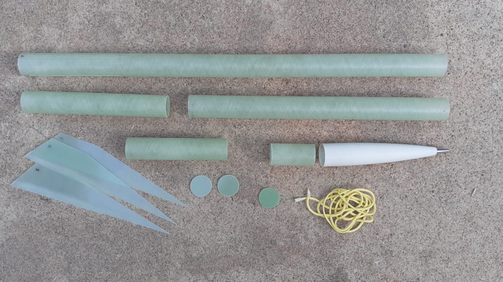
I also purchased the optional Star Cruiser decal, bought the 38mm minimum-diameter retainer from Badass Rocketry (same owners as Mach 1 Rocketry), and eyebolts. The kit will measure almost 60in tall, and the small fins give it a very minimalist, sleek look.

The one issue I observed is that the notch in the fins measured over an inch longer than the slot in the airframe. However, it wasn’t a big deal to Dremel off the excess and reduce the fin notch’s length.

Assembly 1
7/29/21
I began assembly by first cutting a slip band from the payload section and cutting down 2in of the excess motor mount tube, since the fin slots were cut short. I’m using RocketPoxy for almost all of this build. I use some 5-minute on eyebolt threads, and I’ll use West Systems epoxy on the tip-to-tip fiberglass layup. To start today, I was able to epoxy 3 separate parts simultaneously, so it turned out to be a productive first evening of building this kit!
Slip bands are super useful in my opinion, since I tend to put screw switches or switch access holes in the slipband. I measured out where it was to be located, drew a line on both ends in pencil, then wrapped the edge of one line in painter’s tape. Once a very thin layer of epoxy was applied, the slip band pushed on, and the excess epoxy squeezed out onto the painter’s tape. Finally, the painter’s tape can be lifted away, taking almost all the excess epoxy with it and leaving a clean line where the slipband meets the coupler. If any excess is left here, it creates a fillet and will prevent the airframe from resting against the slip band; it will instead come up short from the excess epoxy. With the tape peeled away, this was left to cure! I’ll do the avbay assembly after construction of the rest of the rocket.


I’m not using the nosecone for any electronics, so it’ll become an empty part, epoxied closed. I began the nosecone assembly by drilling out the center of the bulkhead for the 10-24 eyebolt, attaching the washers and nuts, and slathering both sides in epoxy to keep the nuts from coming loose.


Then this eyebolt-bulkhead assembly got epoxied into the coupler. I like to recess the eyebolts pretty far into the couplers so that 1) the nosecone assembly can stand on a tabletop (eyebolt doesn’t protrude), and 2) it gives just a little extra room for shock cord to wad inside. For loose-fitting bulkheads like this one, I made a paper roll out of a sticky note to support the bulkhead from below while the epoxy set. This way, the bulkhead can cure suspended inside the middle of the coupler.

Finally, I slathered some epoxy inside the nosecone and slid the bulkhead-coupler assembly inside. I put epoxy inside the nosecone rather than the outside of the coupler because otherwise the excess would build up outside the nosecone and prevent the nosecone base from fitting against the payload airframe section. By putting epoxy inside the nosecone, the excess got pushed up and into the nosecone. Out of sight out of mind! Nosecone assembly is done. It will only need shear pin holes later.

The final part of tonight’s build session involved epoxying in the motor mount. Although a minimum-diameter kit, this included an inner tube with an ID that matched the 38mm motor OD. I decided to install the tube from top to bottom (unlike most motor mount centering ring assemblies that I install from the aft end), so that excess epoxy would build up at the aft-most end, and I could wipe it away with access. That wouldn’t work out well were I to try this when it is recessed 8 inches inside a narrow tube.
I put a small amount of epoxy in between the fin slots, using a thin metal tube as a stir/applicator stick. I spread it out as thinly as possible, working it into the composite as best I could, knowing most would get pushed out anyway.
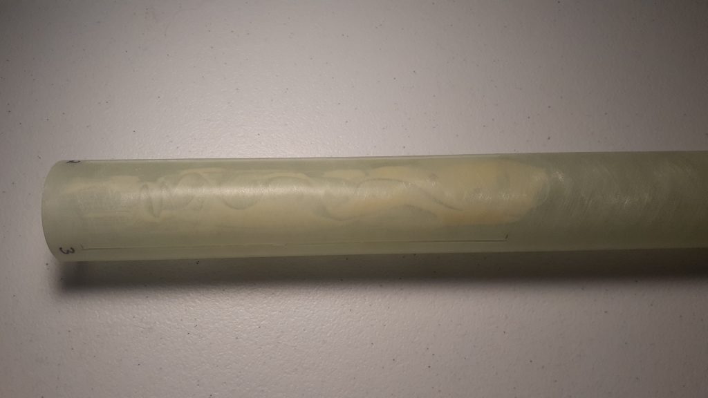

I cleaned up the excess epoxy with isopropyl alcohol and paper towels, making sure to get everything out of the motor mount ID. The fin slots appeared to have remained free of epoxy which was good. With that, I set the assembly up to cure with an old business card underneath to keep the epoxy from adhering to my bathroom counter.
I’m really happy with how these 3 elements all came together today! It sure went faster than having 3 centering rings to bond to a motor mount and then installing that inside the airframe with rail buttons to consider. Fins will come later this weekend!

Assembly 2
8/1/21
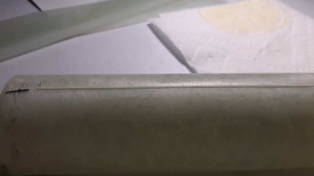
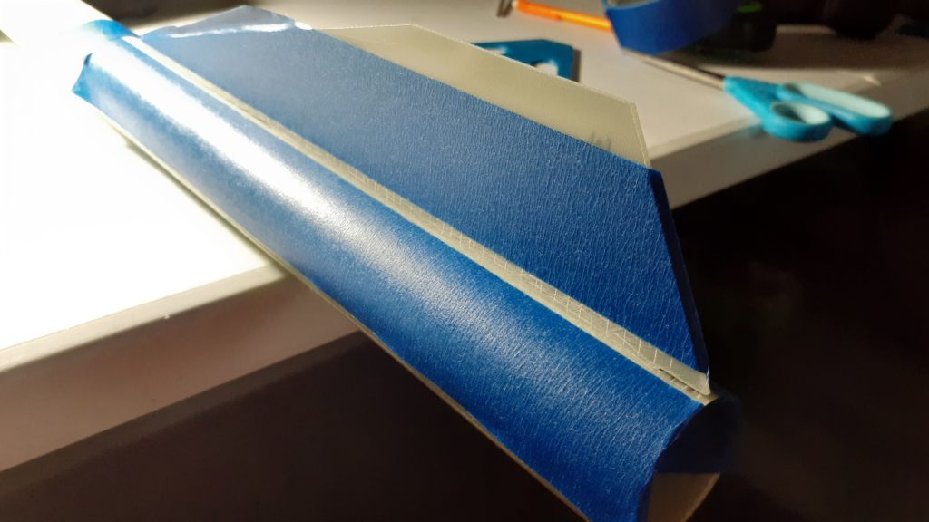
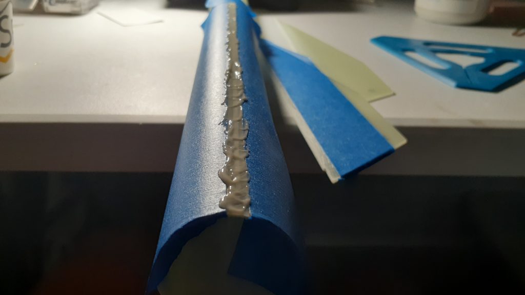
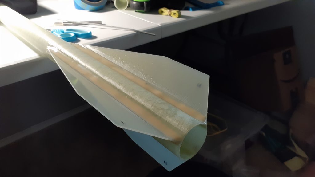
Over the course of this weekend I put on all 3 fins and thick epoxy fillets. I don’t worry too much about making perfect fin fillets, but I still tape off the edges and smooth out any even areas. I roughed up the fins and airframe with 60-grit sandpaper and used an X-Acto knife to make small shallow cuts in the fiberglass. I affixed one fin at a time, using only a small amount of epoxy for the initial joint. After all 3 were attached, I went back around to do the larger fillets. I’ll come back in with some sandpaper and smooth them out some more, but since a tip-to-tip layup will go on after, the surface will be covered up anyway.



Fly-Away Rail Guides
8/16/21
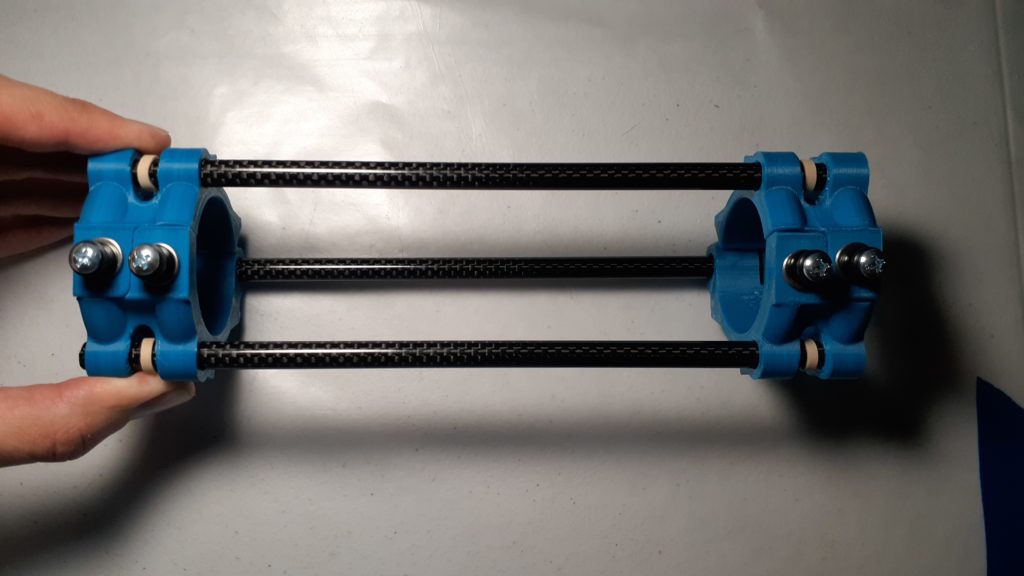
During the cure process of the fin can tip-to-tip fiberglass layup, I put together the fly-away rail guides for this rocket. I’d printed out the attachment points from this Thingiverse file by plainolddave. It came together really well with M3 and M4 hardware, rail buttons, and carbon fiber rods, most of which were purchased on Amazon. These assembled fairly easily, although they’re a little snug against the airframe of the kit. I’ve never used FARGs before, so this first launch will be experimental for multiple reasons!


8/23/21 Update
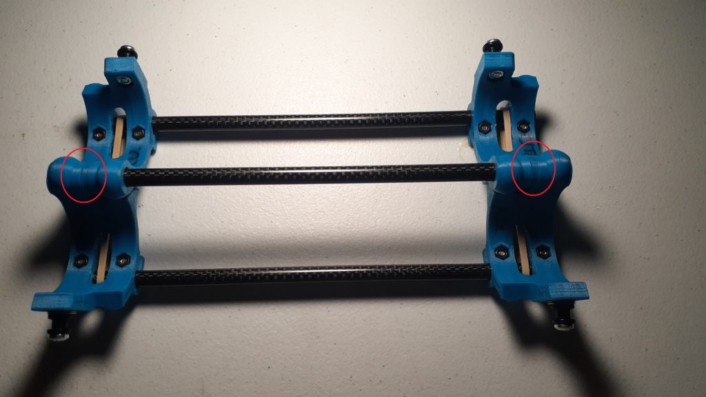
After experimenting with these some more in the days following, I noticed that the jaws just between the fail buttons would snag on one another if the two printed halves were seated flush against one another. That snagging prevented a clean “snap” opening. The fix to this was to space out the printed halves along the common carbon fiber rod by an eight inch or so. However, while this kept the jaws from snagging on one another, the rubber band would bind inside that eighth-inch gap, thereby also preventing a clean opening.
My resolution to both of these issues was to add a small washer between the printed halves, circled below in red. This gave the jaws plenty of offset while also filling the gap previously caused by spacing the printed halves apart. This is a simple washer-like part with an ID of 0.35in (8.89mm) for the carbon fiber rod, an OD of 0.56in (14.22mm), and a height of 0.125in (3.175mm). I’ve included the .STL as a file for download below.


Tip-to-Tip Fiberglass Layup
8/18/21
This wasn’t the first fin can layup I’ve done, but it’s the first one with proper surface preparation and finishing. I utilized some tips from Xyla Folin’s L2 rocket video and BPS.space’s composite fin can video, mostly for the surface prep/finish. I began roughing up the fin and airframes surfaces with 400-grit sandpaper to try and achieve a low break angle of a water break test, but after 4 runs with sandpaper, alcohol, and lint-free wipes, it seemed to have the same high break angle as before.
I proceeded to the layup process anyway by cutting out plies, peel ply, and measuring out the West Systems Epoxy. I only used 2 plies that added up to 10g of cloth, for which I used 12g total epoxy (aiming for a 1 to 1 ratio of cloth to epoxy, plus some excess).

It was awkward mixing such a small amount of the runny resin and hardener, but dipping the popsicle sticks and letting it drip into the cup on the scale did the trick. Rather than wet the plies first and lay them onto the fins, I set the dry ply in place over the fins and worked the epoxy into the cloth with the stir stick and gloved hand. With just 2 layers of cloth, it was a quick process, using gloves let me push the epoxy everywhere necessary, and I laid the peel ply on top. The only areI had trouble with was at the leading edges of where the fin met the airframe. The peel ply didn’t stick as well here either, so on the final of three layups, the plies didn’t completely stick and I got a shallow bubble.


The West System 105-206 took 10-15 hours to cure, at which point I pulled off the peel-ply. The surface underneath wasn’t overwhelmingly smooth, and I sanded it plenty anyway, so I might skip it next time. I used a Dremel cutoff wheel to cut away the excess hardened cloth and then 60-grit sandpaper to clean up the leftover along the leading edges.
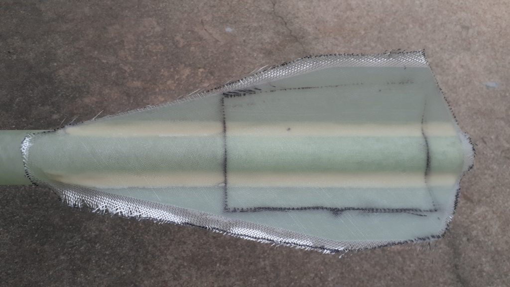
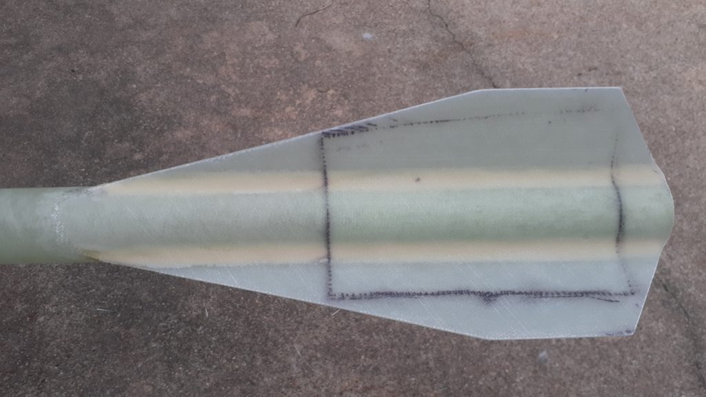
With all 3 fin layups complete, I used 120, 220, 400, and 600 grit sandpaper to clean up all surfaces and make it silky smooth. It didn’t take too long, but I’m sure when I paint it, I’ll find all kinds of surface imperfections. There were a couple voids/indents that opened up during sanding, so I filled those with a little 5-minute epoxy and sanded smooth.

I’m really happy with how it turned out! Each layup added 18g of weight, so 44g of additional weight on the fins to an already barely-stable rocket wasn’t ideal, but I’m just glad I didn’t add additional plies. I think next time I will skip the peel ply, but everything else went well enough I look forward to doing it again on another minimum-diameter build!
Altimeter Bay, Avionics
8/21/21
This build is almost complete! Yesterday I assembled the altimeter bay including the avbay bulkplates, sled, and wiring. I like to tap the sled and bulkplates with 4-40 holes and use nylon screws to affix the altimeter, battery cage, switch, terminal blocks, and ejection charge caps. On small builds like these, I usually skip the ejection charge cap, opting instead for ematch and black powder in the finger of a latex glove ejection charge, but I’ve found using a cap helps direct the gases away from the bulkplate and singes the terminal blocks less.
For all flights of Star Cruiser, I’ll use a TeleMetrum for dual deployment and GPS tracking with its integrated telemetry link to a Teledongle ground station. It is powered by an 850mAh li-po and uses a 6-32 screw switch mounted to the sled. To access the switch, I have a 5/32 hole in the slipband that I’ll insert a screw driver through to arm, then plug the hole with a plastic rivet prior to flight. The hole, were it to remain open, would be oversized for the small avbay volume.
I designed the sled specifically for this rocket and printed it from ABS plastic. It uses a single threaded rod offset from the center to maximize the centerline volume. Finally, I also added a JST connector for the main ejection charge connection, just for ease of use.

Ejection Charge Testing
8/21/21
This afternoon I ejection charge tested the whole rocket, now that the avbay is complete. I used 0.3g charges for both apogee and main, and this turned out to not be enough. It was sufficient for Easy on the Wallet Too, but Star Cruiser uses 2x 2-56 shear pins instead of 1/16 styrene rods. I think that had something to do with it, but I’d also forgotten a vent hole in each section. I upped the charges to 0.7g and 0.5g for drogue and main, respectively, and that did the trick. The 0.7g was probably excessive, but as loud as it was, it’ll be helpful to hear at apogee.
All that’s left is a simple paint job, and then it should be all set for flight!

Paint and Decal
8/28/21
This past week I put the finishing touches on this project including the paint job, decal, and clear coat. I had a tiny bit of white primer left that I put on the fiberglassed fin can, and it was here that I found out just how many pinholes/unsaturated fiberglass I had. It definitely warranted more epoxy, especially at the leading edge of the layup, but I didn’t feel like trying to fill them all in, so I painted the whole thing black in 2 coats. It wasn’t the best quality paint or the best painting conditions, but I’m expecting it the get plenty dinged up after repeated flights that a flawless-looking rocket wasn’t my goal.
48 hours after applying the last of the black paint, I put on the included decal from Mach I Rocketry which gave it a super clean look. I added my contact information, labeled the CP, and marked the avbay and nosecone alignment areas in silver Sharpie on the back. I rounded out the last of the surfaces with a light coat of clear coat that helped give it a smoother finish than the cheap paint did. That’s it! All that remains is its first flight next weekend at Airfest 27! It’ll go up on an H123W to about 3000ft.


